
The default source block settings in the spectrometer_w_cal.grc GNU Radio program are for the Airspy R2 SDR. A different SDR may require changes to the source and samp_rate Variable blocks. Sometimes the freq Variable block also needs changes. The settings for some common SDR’s used with the horn telescopes are described below.
Why
freqsometimes has to change too. The program records a bandsamp_ratewide, centered onfreq. The defaults arefreq1419 MHz andsamp_rate10e6. This records 1414 to 1424 MHz, comfortably including the hydrogen line at 1420.4058 MHz. Reducing the sample rate shrinks the band around 1419 MHz. Without retuning the center, the hydrogen line eventually falls outside that band. Set the sample rate to 2.4e6 and the band becomes 1417.8 to 1420.2 MHz. The line lies about 0.2 MHz outside it. The telescope records no hydrogen. The RTL-SDR and Pluto settings therefore changefreqtoo. The Airspy Mini and Lime settings do not.Your band runs from
freq - samp_rate/2tofreq + samp_rate/2. It must include 1420.4058 MHz with room to spare at both ends.
Options:
-
The Airspy Mini
-
Source block: the
osmocom Sourceblock is used; the “Device Arguments” are the same as for the Airspy R2. So no changes are needed in this block. -
samp_rate Variableblock: Find it besideOptions, at the canvas’s upper left inspectrometer_w_cal.grc. Open this block by double-clicking it. Change the “Value” to “6e6” (which is 6 MHz).
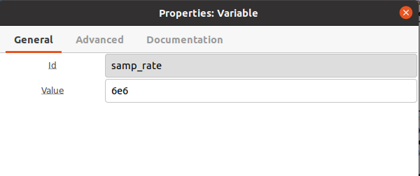
freq Variableblock: leave it at 1419e6. The band becomes 1416 – 1422 MHz, which still holds the line.
-
-
RTL-SDR
Two changes are needed, not one. The
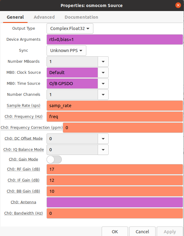
samp_ratechange alone moves the hydrogen line out of the recorded band — see the box above. Make both.- Source block: Change the “Device Argument” to: rtl=0, bias=1, pack=0, as shown:
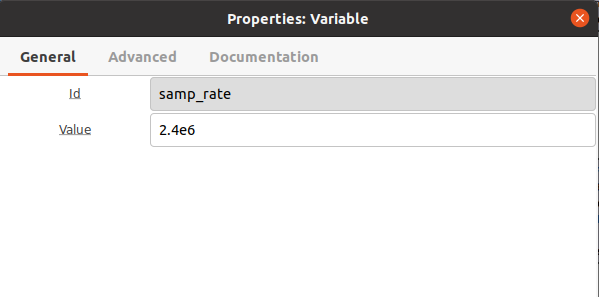
samp_rate Variableblock: Find it besideOptions, at the canvas’s upper left inspectrometer_w_cal.grc. Open this block by double-clicking it. Change the “Value” to “2.4e6” (which is 2.4 MHz).
-
freq Variableblock: next tosamp_rate. Change the “Value” to “1420.5e6”. The band then runs 1419.3 – 1421.7 MHz, with the line at 1420.4058 MHz inside it. -
An RTL-SDR has two limitations at this sample rate. Neither can be fixed in the flowgraph:
- The band covers only about ±230 km/s, clipping the line’s faint wings. No region is guaranteed free of Galactic hydrogen for baseline fitting. Maps are good for seeing where the Milky Way is; treat the intensity numbers as indicative.
- These SDRs produce a spurious tone at the band’s exact center. At this tuning, it sits 0.1 MHz from the line.
map_h1_hdf5_drift.pyblanks a 120 kHz strip around it. The strip’s proximity to the line costs roughly one quarter of the measured intensity. The comment onDC_MASK_HALFWIDTH_HZin that script has the measured figures and the two ways to improve it.
-
Lime
- Source block: the Lime uses the
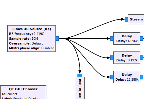
LimeSDR Source (RX)block. Click on theosmocomblock and hit Delete. Then in the search window on the tool bar at the top, type “LimeSDR”. Grab theLimeSDR Source (RX)and drag it onto the canvas where theosmocomblock was. Connect the blue output ofLimeSDR Source (RX)toStream to Vector. Also connect it to the threeDelayblocks andComplex to Real. The final connections should look like the following:
- Open the
LimeSDR Source (RX)block (by double-clicking) and set the following:- On the “General” tab, set “RF frequency” to “freq” [without the quotes]. Check that “Sample rate” is “samp_rate” [without the quotes]. “Channel” should be on “A” [without the quotes].
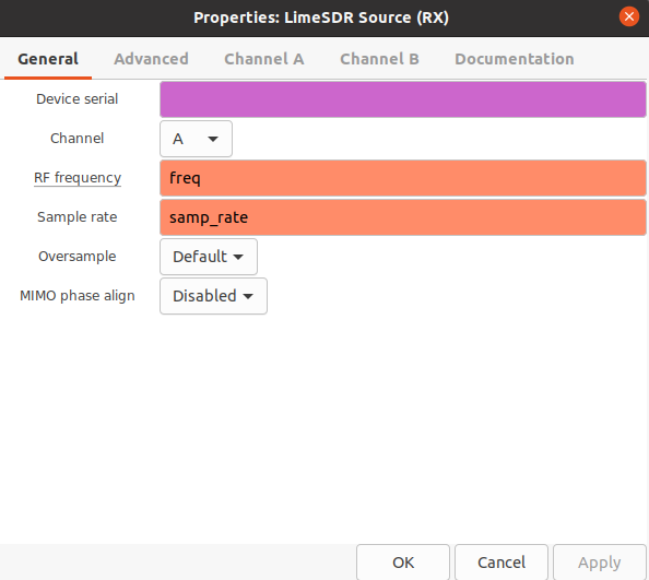
- The settings on the Channel A tab should be as shown:
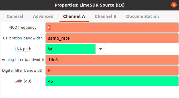
-
samp_rate Variableblock: The Lime SDR can use a 10 MHz samp_rate; so no change is needed in this block. Leavefreqat 1419e6 as well — the band stays 1414 – 1424 MHz, the same as the Airspy R2. -
Install gr-limesdr - software needed for the Lime SDR block to run in GNU Radio.
-
Open a terminal window.
-
Type and enter:
sudo apt install gr-limesdr
-
-
POWER TO THE LNA: The Lime SDR does not power the LNA. Supply external +5 V dc power through a bias-T. Connect it to the LNA and Lime as shown:
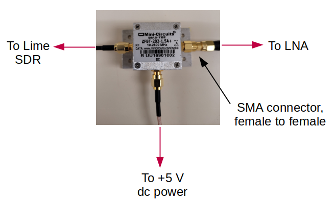
Use an SMA female to female connector/adapter between the bias-T and LNA cable. Follow the diagram above.
- Source block: the Lime uses the
-
ADALM-PLUTO
-
The Adalm-Pluto SDR uses the
PlutoSDRSourceblock that will need to be installed. Complete the steps outlined here to install this block on your computer. -
Source block: the Adalm-Pluto uses the
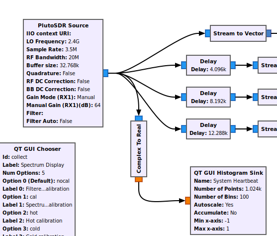
PlutoSDRSourceblock. Click on theosmocomblock and hit Delete. Then in the search window on the tool bar at the top, type “PlutoSDR”. Grab thePlutoSDRSourceand drag it onto the canvas where theosmocomblock was. Connect the blue output ofPlutoSDRSourcetoStream to Vector. Also connect it to the threeDelayblocks andComplex to Real. The final connections should look like the following:
- Open the
PlutoSDRSourceblock (by double-clicking) and set the following:- On the “General” tab, set the values as shown:
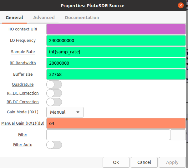
-
The
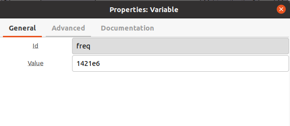
samp_rateandfreqVariable blocks should be set to the values shown —samp_rate3.5e6 andfreq1421e6. Both changes are needed. A 3.5 MHz band centered at 1419 MHz ends at 1420.75 MHz and clips the line. At 1421 MHz the band is 1419.25 – 1422.75 MHz.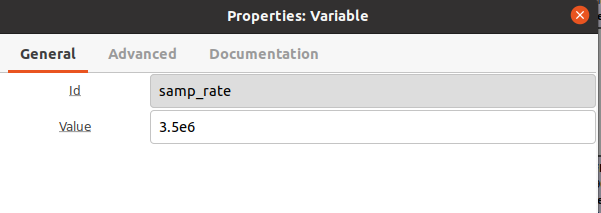
-
POWER TO THE LNA: The Pluto SDR does not power the LNA. Supply external +5 V dc power through a bias-T. Connect it to the LNA and Pluto SDR as shown:
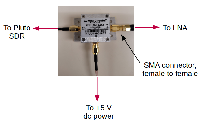
Use an SMA female to female connector/adapter between the bias-T and LNA cable. Follow the diagram above.
-
Cable Hardware: A coaxial cable is needed to connect the LNA to the SDR. Typically a 10 ft length is adequate, but any length up to 25 ft should work fine.